Return to the top page of the manual

Tool menu of Minimal Board Editor

Commands of the tool menu.

Selector Select objects with this tool. Detail
Connection Check Highlighten the connected net. Detail
Measure Measure distance between two point Detail
Hole Place drill holes (No plated hole) Detail
PTH Place plated thru holes Detail
Pad/Flash Place pads or flash(has area but no length) data. Detail
Line Place lines. Detail
Arc Place arcs or circles. Detail
Text Place text data. Detail
Polygon Place plygon of copper pour. Detail
Component Place components which is contained in library.
Detail

Selector

Selector tool is the start of the editing.
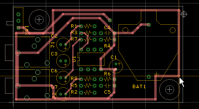
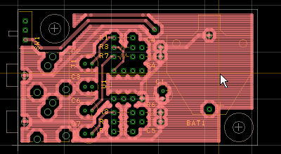
The basic operation of the selector tool is "enclose cross marks of objects".


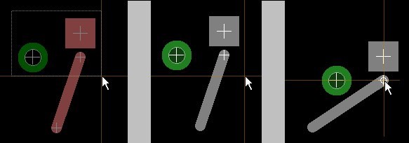
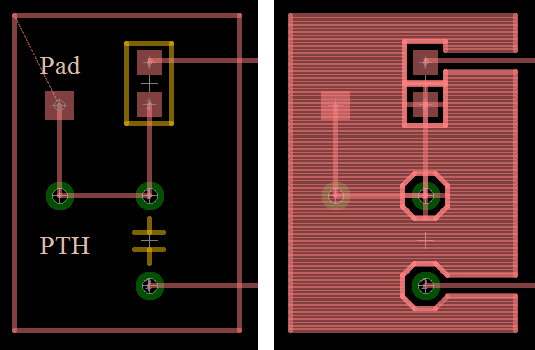
For example, figures above show the selection and the movement of objects.
Each of objects has cross mark(s) at the center or the end of it.

(1)Choose the selector tool
(2)Drag to create a rectangle to enclose cross mark(s). (the left figure)
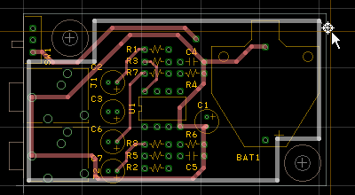
(3)Selected objects and cross marks is highlighted. (the center figure)
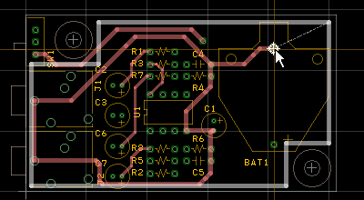
(4)Move the cursor to the one of the selected cross mark(s). The cross mark displays a circle indicator. Then drag them.


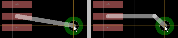
To select a single object.
You can select a single object by clicking.
If a number of objects lap over at the same position, to select a desired object...

Add object(s) to the selected objects
  Select the object(s) with holding down the control key.
  

Connection Check tool

It checks connection of PADs, PTHs, Lines, etc, based on the drawing guideline.

(1)Choose the connection check tool
(2)Click a PAD, PTH or Line.
(3)Connected objects are highlighted.

It recognizes that objects are connected when places of cross marks of them are corresponding.
This rule applies to exporting netlist, too.

The overlapped objects without corresponding cross marks are recognized as gap error on DRC.

Measure

(1)Choose the measure tool.
(2)Click at a point to start measuring distance.
(3)Move mouse. X, Y length and distance are displayed under cursor.
Version 0.51.07 or lator

(4)By moving mouse and clicking, you can measure the total length of points.

Hole tool

You can place drilled holes (non plated thru holes) on the DRL layer.
There are influences in the STC layer and the STS layer, if the drilled hole is placed.

(1)Choose the hole tool
(2)Click on the work area.
(3)A drilled hole is placed.

If you click the right button on the work area, "Set hole"dialog box appears.

After the hole is placed, to change the property of it...

PTH tool

You can place plated thru holes on the PTH layer.
There are influences in the DRL layer, the STC layer and the STS layer, if the PTH is placed.

(1)Choose the PTH tool
(2)Click on the work area.
(3)A PTH is placed.

If you click the right button on the work area, "Set PTH"dialog box appears. You can set the form, the pad size, the diameter of drill, etc.


After the PTH is placed, to change the property of it...

Pad/Flash tool


You can place pads on the CMP layer or the SOL layer.
You can place flash data on the PLC layer or hte PLS layer.

place it on influenced
PLC -
CMP STC, MMC
SOL STS, MMS
PLS -

(1)Choose the Pad/Flash tool
(2)Click on the work area.
(3)A Pad/Flash is placed.


If you click the right button on the work area, "Set Pad/Flash"dialog box appears. You can set the form, the pad size, etc.


After the Pad/Flash is placed, to change the property of it...

Line tool

You can place lines except the PTH layer and the DRL layer.
There is no influence to the other layers.

(1)Choose the Line tool
(2)Click at the start position.
  It can be canceled with the ESC key.
(3)Click at the end positon.


If you click the right button on the work area, "Set Line"dialog box appears. You can set the line width.


Combination key

If you hold down the Shift key or the Ctrl key when placing lines, the line is placed as the bending mode.

combinaton key start end
Shift vertical/horizontal 45 degree
Ctrl 45 degree vertical/horizontal


The figure above is an example for connecting a Pad(it is placed on 1mm pitch grid) and a PTH(it is placed on 2.54mm pitch grid), by using the bending mode line


After the line is placed, to change the property of it...

Arc tool

You can place arcs except the PTH layer and the DRL layer.
There is no influence to the other layers.

(1)Choose the Arc tool
(2)Click on the work area.
(3)An Arc line is placed.


If you click the right button on the work area, "Set Arc"dialog box appears. You can set the line width, the diameter, the start angle and the end angle.

After the arc is placed, to change the property of it...
The difference between the start angle and the end angle cannot be set to less than 10 degrees or more than 350 degree.

Text tool

You can place text objects except the PTH layer and the DRL layer.
There is no influence to the other layers.

(1)Choose the Arc tool
(2)Click on the work area.
(3)Text dialog box appears.
(4)Set text and properties
(5)Close the dialog box with the OK button.
(6)The text is placed temporarily. (7)Click on the work area (but not on the text object).


After the PTH is placed, to change the property of it...
If the text object is placed on the DOC layer, it is drawn with Windows font.
If it is placed on the other layers, it is drawn with the board font.

Polygon tool

In the condition that the drawn patterns are complex, the update of filling pattern of the polygon takes much time.
You can place polygons on the PTH layer, the L2 layer, the L3 layer and the SOL layer.
There is no influence to the other layers.

(1)Choose the Polygon tool
  View mode is changed to "Polygon frame mode" forcibly.

(2)Clicking on the work area places a vertex of the polygon.
  It can be canceled with the ESC key.

In the figure above, the one pointed by the red arrow is a target mark.

(3)You can finish placing the polygon by double clicking.


(4)Choose the selector tool and click the target mark.


(5)Drag the target mark to a Pad or a PTH which you want to connect to the polygon.


(6)Check off [View]-[Polygon frame mode]

In this case, filling takes 2 or 3 seconds. (using Celeron 2.4GHz)
You can see floating patterns, in the figure above.

Here is a procedure not to generate the floating pattern.

(7)Check on again [View]-[Polygon frame mode]
(8)Choose the selector tool and click the frame of the polygon to select it singlely.
(9)[Edit]->[Property]
(10)In the Set Polygon dialog box, check on "Remove floating pattern"
(11)Check off [View]-[Polygon frame mode]

The update of filling will occur, when ...
If you execute [File]-[Open], [File]-[Save] or [File]-[Save As], the view mode is changed to "Polygon frame mode".
You can select a polygon placed on work area with the Selector tool, when view mode is "Polygon frame mode".
Properties of polygon
A Component can not contain a polygon.
About thermal relief


Component tool

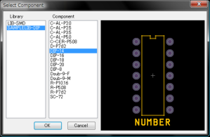
This tool is enabled when libraries are registered by "[Set]-[Library]".

You can place components on the CMP layer and the SOL layer.

(1)Choose the Component tool.
(2)Click on the work area.
(3)Select Component dialog box appears.
(4)Select a library and compnent.
(5)Close the dialog box with clicking OK.

(6)The component is placed temporarily.